

Twin Lights Behind the Grill Version
Click image to enlarge wiring instructions


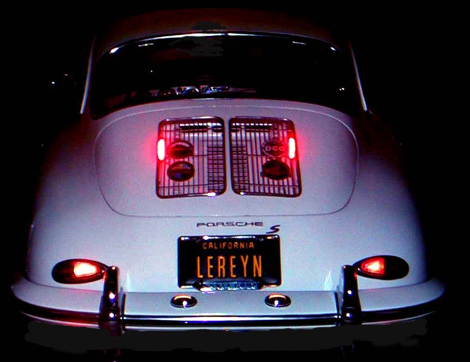
These Lights may be wired to function as Brake Lights, Tail Lights or Turn Signal Lights.
The Twin Lights are assembled using 12 bright LED’s each, mounted within a plastic housings measuring three and ½ inches long, ½ inch high and ¾ inch deep. They mount on each side of the grill(s) are held in place by the mounting between the grill and deck lid. (3 inches distance between the top of the grill to the inside panel is required.) The wiring is routed to the master cylinder brake light switch, rear taillight or the front turn signals. Typical installation time is about one and ½ hours. Tools required are a pair of pliers a screwdriver and a wrench for grill removal.
Third Brake Light Flasher Unit
Adjusts from full on or 2-20 flashes /second.
Works with 6 volts or 12 volts.
Size: 1 1/4 inch square X 7/8 inch high X 3/8 oz.
 |
| Unit will support up to 2 Light products. |
Wiring Instructions:
1. Unit placement:
Locate the wire which is connected from the master cylinder brake switch to the Third Brake Light.
Pick a location near the wire run for the flasher placement.
Locate the wire which is connected from the master cylinder brake switch to the Third Brake Light.
Pick a location near the wire run for the flasher placement.
Keep in mind that you might want to easily adjust the flashing frequency.
Cut the wire into.
2. + Voltage wire routing of the Third Brake Light:
Connect the wire end from the master cylinder brake light switch to the appropriate connection on the flasher unit.
Attach the wire end from the Third Brake Light to the appropriate connection on the flasher unit.
Wrap each connection with the supplied electrical tape.
3. Chassis ground wire routing from the flasher:
Route the black ground wire from the flasher unit to a chassis mounting fastener and attach the ring lug.
Clean the chassis surface around the fastener area.
Place the ring lug between the chassis and fastener and tighten.
4. Check for functionality and set the desired interval.
posted by Sally Biersdorff | 3:46 PM
![]()
<< Home